





Plain answers on testing a fuse (continuity), a diode (diode-test mode) and a capacitor (capacitance mode), including why capacitance alone cannot catch a high-ESR electrolytic.
Fuses, diodes and capacitors are cheap, common and the first suspects when a device goes dark. They are also easy to misjudge. A meter set to the wrong mode returns a number that looks reasonable and means nothing, and Fluke lists ignoring the meter mode as a common mistake that “can lead to false readings.”
The answers below follow Fluke’s published guides for each part, with two Wikipedia articles filling in what a capacitance reading cannot tell you. Anyone building from a starter box such as the one in our Elegoo UNO R3 kit review will meet all three parts quickly.
How do you test a fuse with a multimeter?
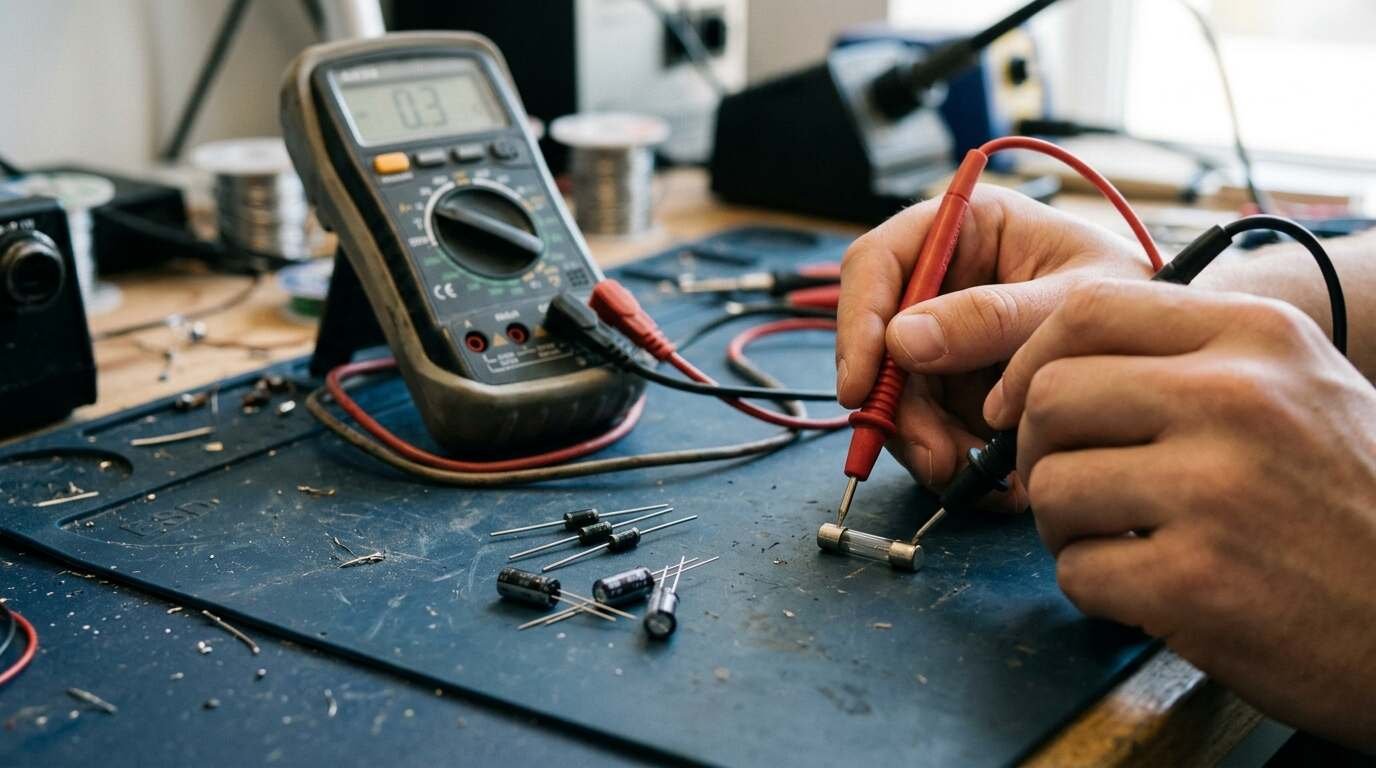
Start with the power. Fluke’s fuse guide says the circuit must be powered off and disconnected from any power source, and recommends PPE such as insulated gloves and safety glasses. Then set the meter to continuity or resistance. Continuity is “generally preferred.” Touch the probes together first: continuity should beep, and resistance should read near zero.
Place a probe on each end of the fuse with firm, stable contact. A beep means a complete path, so the fuse is good. Silence means it is blown. In resistance mode, a reading near 0 ohms means the fuse is intact, and an infinite reading, shown as “OL” or “1,” means it is blown. Fluke also suggests looking for a broken internal wire or a darkened, burnt appearance.
Where you touch depends on the fuse. Glass tube and ceramic types come out of the holder or circuit, with probes on the metal caps. Blade fuses are disconnected from the fuse box, with probes on the metal prongs.
Can you test a fuse while it is still in the circuit?
Fluke’s type-specific steps all begin by removing or disconnecting the fuse, and the article does not discuss in-circuit testing. That is a gap in the source, not a green light. Pulling the fuse also removes parallel paths that could confuse a resistance reading, though Fluke does not state that reasoning; treat it as an inference.
How do you test a diode?
Use Diode Test mode. Fluke’s diode guide calls it “almost always the best approach,” with resistance mode reserved for meters that lack the setting. Make sure all power to the circuit is off and that no voltage exists at the diode. In some cases one end of the diode must be lifted from the circuit, and resistance-mode readings should never be taken on a diode that is still connected, since they can be false.
Put the red lead on the anode and the black lead on the cathode for forward bias, then swap them. Fluke’s expected results are below.
| Reading | What it means (per Fluke) |
|---|---|
| Forward 0.5 to 0.8 V, reverse OL | Good silicon diode |
| Forward 0.2 to 0.3 V, reverse OL | Plausible for some germanium diodes |
| OL in both directions | Open diode |
| About 0.4 V in both directions | Shorted diode |
| Forward 1000 Ω to 10 MΩ, reverse OL (resistance mode) | Good diode, though this mode does not always indicate good or bad; compare with a known good part |
Fluke’s page does not discuss LEDs, so this guide does not either. Check a meter manual before assuming LED behaviour matches the silicon figures.
How do you measure a capacitor in capacitance mode?
Discharge it first. Fluke’s capacitance guide warns that a good capacitor “may remain energized after power is removed.” Its sequence: confirm with the meter that all power is off, then connect a 20,000 Ω, 5-watt resistor across the terminals for five seconds, and confirm with the meter that the capacitor is fully discharged.
Turn the dial to capacitance, pressing a function button if the meter needs one. Detach the capacitor from the circuit, since Fluke says that avoids measurement errors. Connect the leads and hold them there for a few seconds so the meter can pick a range. An “OL” display means the value exceeds the range or the capacitor is faulty. For small values, Fluke recommends Relative mode to subtract the capacitance of the test leads.
Compare the display with the value printed on the part. Fluke notes that deterioration can change capacitance. Tolerance is the allowed deviation of measured capacitance from the rated value, per Wikipedia’s electrolytic capacitor article, which also gives the standard measuring condition for electrolytics as 0.5 V AC at 100/120 Hz and says a 1 kHz reading runs about 10 percent lower. A meter that tests at another frequency may therefore disagree slightly with the label even when the part is fine; the meter’s manual should state its test conditions.
Why can a capacitor pass and still be bad?
Because capacitance is only one property. Wikipedia’s equivalent series resistance article defines ESR as the resistance an ideal capacitor would carry in series, and warns that ESR can rise enough to cause circuit malfunction and even component damage. For aluminium electrolytics, it says ESR rises with age as electrolyte is lost, which it calls a very serious problem.
The ESR meter article puts the practical consequence plainly: standard capacitance meters cannot measure ESR, and an ESR meter does not measure capacitance. In aluminium electrolytics, excessive ESR is far more likely to be the identifiable problem than out-of-tolerance capacitance. The same article says ESR meters are typically used without disconnecting the capacitor from the circuit.
So a multimeter capacitance test can condemn a dead capacitor but cannot clear a tired one. If the symptom points at a power supply rail and the capacitance reads fine, ESR is the remaining suspect. The sources do not give a pass/fail ESR threshold; that figure comes from the capacitor’s datasheet.
Should a new fuse or an old meter be trusted?
Neither automatically. Fluke advises testing new fuses before installing them, and calibrating the multimeter regularly. The probe-touch check from the first section doubles as a quick sanity test of the leads and the mode: if shorted probes do not beep or read near zero, no later reading on that setup means anything. In professional settings, Fluke also recommends documenting findings.
What does OL mean?
Its meaning depends on the mode. On a fuse in resistance mode, Fluke treats “OL” or “1” as an infinite reading, so the fuse is blown. On a diode in reverse bias, OL is the expected, healthy result. In capacitance mode, OL means the value is above the range or the capacitor is faulty. One symbol, three verdicts; read the mode before reading the display.
Quick reference
| Part | Meter mode | Healthy result | Main caution |
|---|---|---|---|
| Fuse | Continuity or resistance | Beep, or about 0 ohms | Remove it and power down first |
| Diode | Diode Test | 0.5 to 0.8 V forward (silicon), OL reverse | Lift one end if still in circuit |
| Capacitor | Capacitance | Within tolerance of the rated value | Discharge through a resistor first; ESR is not measured |
What are the safety limits?
- Power off and confirm it is off, for all three tests (Fluke).
- Discharge capacitors through a resistor before touching them (Fluke).
- Never connect an ESR meter to a capacitor holding significant voltage; the ESR meter article warns it can be damaged by residual charge or a live circuit.
- Electrolytics have polarity: Wikipedia says they must be operated with the anode more positive than the cathode, and that reverse polarity or overvoltage can damage the dielectric and cause catastrophic failure.
- Failure of electrolytic capacitors “can result in an explosion or fire,” according to Wikipedia, so do not leave a suspect part energized.
For another example of purpose-built test gear that measures what a basic meter cannot, see our look at the Fluke acoustic camera.
Sources