





A MicroPython tutorial for a Pico W web page that shows temperature, using the on-chip sensor or a DS18B20, with code adapted from Raspberry Pi and MicroPython documentation.
The Raspberry Pi Pico W puts a Wi-Fi radio on the same small board as a microcontroller, which makes a self-hosted temperature page a short project: read a sensor, open a socket, answer a browser. The finished page lives on the local network and shows one number that refreshes whenever the browser does.
Two sensor routes are covered. The first uses the temperature sensor built into the RP2040 chip, which needs no extra parts. The second uses a DS18B20 probe on a one-wire bus. Every API call below appears in Raspberry Pi’s own documentation or the MicroPython RP2 quick reference; this is a guide built from those documents, so adapt pins and credentials to your own setup.
What you need
- A Pico W (or another Wi-Fi-equipped Pico-series board) and a USB cable.
- A computer with Thonny, or any tool that can copy a file to the board.
- Optional: a DS18B20 sensor and a 4.7 kΩ resistor. The MicroPython documentation says to connect that resistor between the data pin and the power pin.
- A network name and password you are allowed to use.
Anyone starting from scratch with the Pi family may also like our CanaKit Raspberry Pi 5 starter kit review and the guide to setting up a Raspberry Pi home server.
Step 1: install MicroPython
Raspberry Pi’s Python SDK guide (section 1.2) describes the process. Remove all power from the board, hold down the BOOTSEL button while plugging in the USB cable, and a drive called RPI-RP2 appears. Drag the MicroPython firmware.uf2 file onto that drive. Programming takes a few seconds, then the board reboots into MicroPython and the drive disappears.
In Thonny (section 4.1), click the interpreter name at the bottom right and choose “MicroPython (Raspberry Pi Pico W).” Saving a file to the board as main.py makes it run automatically when power is applied.
Step 2: read the onboard sensor
The Python SDK guide (section 3.3) states that the ADC’s fifth input channel connects to a temperature sensor built into the RP2040. Channels count from zero, so the sensor is channel 4. The guide’s example reads it and applies the conversion shown here.
import machine

sensor = machine.ADC(4)
conversion_factor = 3.3 / 65535

def read_temp_c():
    reading = sensor.read_u16() * conversion_factor
    return 27 - (reading - 0.706) / 0.001721
The function body mirrors the Raspberry Pi example. read_u16() returns an integer from 0 to 65535, per the MicroPython machine.ADC reference. A caveat on naming: the current MicroPython RP2 quick reference describes the constructor as accepting a channel from 0 to 3 or ADC.CORE_TEMP for the internal sensor, so if ADC(4) fails on a newer firmware build, try that constant.
Because this sensor sits inside the processor package, the figure describes the chip, and the guides do not claim it matches room temperature. For a reading of the air, the DS18B20 option in step 5 is the better fit; that last sentence is this guide’s opinion rather than a documented fact.
Step 3: join the network
The connection routine below is taken from section 3.6 of the Pico W networking guide. It activates the interface, connects, waits up to ten seconds, and stops with an error if the status is not 3.
import time
import network

ssid = 'Wireless Network'
password = 'The Password'

wlan = network.WLAN(network.STA_IF)
wlan.active(True)
wlan.connect(ssid, password)

max_wait = 10
while max_wait > 0:
    if wlan.status() < 0 or wlan.status() >= 3:
        break
    max_wait -= 1
    print('waiting for connection...')
    time.sleep(1)

if wlan.status() != 3:
    raise RuntimeError('network connection failed')
else:
    print('connected')
    status = wlan.ifconfig()
    print('ip = ' + status[0])
One naming note: the MicroPython WLAN reference now documents the station constant as network.WLAN.IF_STA, while the Raspberry Pi guide uses network.STA_IF. The status constants on that page name STAT_GOT_IP as the successful state.
Step 4: serve the reading
Section 3.9.1 of the networking guide contains a small static-page server. The version here keeps its structure and swaps in the temperature. It opens a socket on port 80, accepts a connection, reads the request lines until a blank one, then sends an HTTP 1.0 response.
import network
import socket
import time
import machine

ssid = 'Wireless Network'
password = 'The Password'

sensor = machine.ADC(4)
conversion_factor = 3.3 / 65535

def read_temp_c():
    reading = sensor.read_u16() * conversion_factor
    return 27 - (reading - 0.706) / 0.001721

wlan = network.WLAN(network.STA_IF)
wlan.active(True)
wlan.connect(ssid, password)

max_wait = 10
while max_wait > 0:
    if wlan.status() < 0 or wlan.status() >= 3:
        break
    max_wait -= 1
    print('waiting for connection...')
    time.sleep(1)

if wlan.status() != 3:
    raise RuntimeError('network connection failed')
else:
    print('connected')
    status = wlan.ifconfig()
    print('ip = ' + status[0])

addr = socket.getaddrinfo('0.0.0.0', 80)[0][-1]
s = socket.socket()
s.bind(addr)
s.listen(1)
print('listening on', addr)

head = '<!DOCTYPE html><html><head><title>Pico W</title></head><body><h1>Temperature</h1><p>'
tail = ' C</p></body></html>'

while True:
    cl = None
    try:
        cl, addr = s.accept()
        print('client connected from', addr)
        cl_file = cl.makefile('rwb', 0)
        while True:
            line = cl_file.readline()
            if not line or line == b'\r\n':
                break
        temp = int(read_temp_c() * 10) / 10
        cl.send('HTTP/1.0 200 OK\r\nContent-type: text/html\r\n\r\n')
        cl.send(head + str(temp) + tail)
        cl.close()
    except OSError as e:
        if cl:
            cl.close()
        print('connection closed')
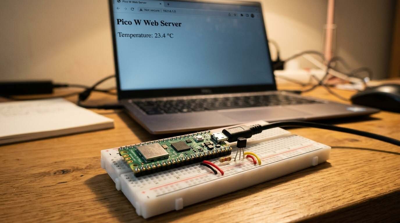
Save it as main.py, reset the board, and watch the Thonny shell for the line starting “ip =”. Enter that address in a browser on the same network. Each reload triggers a new sensor read, because the reading happens inside the request loop.
Step 5: use a DS18B20 instead
The RP2 quick reference lists the one-wire pattern. Create the bus on a GPIO pin, scan for devices, start a conversion, wait, then read. The MicroPython one-wire tutorial says a conversion must be initiated with convert_temp() and that at least 750 ms must pass before reading.
import time
import onewire
import ds18x20
from machine import Pin

ow = onewire.OneWire(Pin(12))
ds = ds18x20.DS18X20(ow)
roms = ds.scan()

def read_temp_c():
    ds.convert_temp()
    time.sleep_ms(750)
    return ds.read_temp(roms[0])
Replace the earlier read_temp_c() with this one and delete the ADC lines. GPIO 12 is the pin used in the documentation example; any free GPIO works if you change the number. A BME280 would need a driver from outside the core MicroPython documentation, so this guide leaves it out rather than publish unchecked code.
Troubleshooting the connection
When the script raises “network connection failed,” the status value says why. The MicroPython WLAN page defines the codes, and the Raspberry Pi example treats any negative value as a failure.
| Status constant | Meaning (MicroPython WLAN page) | What to check |
|---|---|---|
| STAT_WRONG_PASSWORD | Failed due to incorrect password | Retype the password in the script |
| STAT_NO_AP_FOUND | No access point replied | Name spelling and signal range |
| STAT_CONNECT_FAIL | Failed due to other problems | Router settings; try again |
| STAT_CONNECTING | Connection in progress | The ten-second wait may be too short; raise max_wait |
| STAT_GOT_IP | Connection successful | Nothing; the IP address prints next |
Print wlan.status() just before the error to see the number. The last column is this guide’s suggestion, not a documented remedy.
How the pieces fit together
The ADC returns a raw count; multiplying by 3.3 divided by 65535 turns it into volts, since the MicroPython quick reference says read_u16() spans 0 to 65535 across 0.0 V to 3.3 V. The Raspberry Pi example then converts volts to degrees with the 27 and 0.706 constants shown above. Those constants come from that example, and this guide has not independently checked them against the RP2040 datasheet section on the sensor.
Limits and cautions
- The server handles one connection at a time (listen(1)), and the example is written for a trusted home network.
- Do not forward port 80 to the internet. That is a security recommendation from this guide, not from the cited documents.
- The DS18B20 code assumes one probe on the bus; roms[0] picks the first device found.
- Rewrite the credentials before publishing any copy of the file.
Parts list
- Pre-Soldered Header Raspberry Pi Pico W, Built-in WiFi Support 2.4 GHZ Wi-Fi 4, Based on Official RP2040 Dual-Core Processor, Dual-core Arm Cortex M0+ Processor, Comes with Pico W Board and Case: A Pico W board with pre-soldered headers and a case, so it drops straight onto a breadboard. See it on Amazon (affiliate link)
As an Amazon Associate I earn from qualifying purchases. A commission may be earned if you buy through this link, at no extra cost to you.
Sources