





A build guide for an Arduino tachometer using a Hall switch and a magnet: how the sensor responds, interrupt-based pulse timing, the RPM arithmetic worked out, and noise guards.
Thirty-seven and a half milliseconds. That is the gap between two pulses when a shaft with one magnet on it turns at 1,600 revolutions per minute, and it is the only number an Arduino tachometer really needs to measure. Everything else in the build exists to measure that gap cleanly.
Below is a build guide for a Hall-effect tachometer on an Arduino Uno: how the sensor reacts to a magnet, how an interrupt timestamps each pulse, the arithmetic that turns a period into RPM, and what to do about noise. Spec figures come from the Allegro A3141 to A3144 datasheet and the Arduino reference pages.
How a Hall sensor answers a magnet
In a Hall element, a bias current runs along a thin conductor, and a magnetic field perpendicular to that current deflects the charge carriers sideways. The resulting voltage across the strip tracks the field component, as the Wikipedia article on Hall effect sensors explains. The raw signal is tiny, so sensor chips add an amplifier, and switch types add threshold detection to give an on/off output.
The A3144 is that switch type. Its datasheet lists a 4.5 to 24 V supply and an open-collector output that sinks up to 25 mA. The output goes low when the field at the Hall element exceeds the operate point (BOP) and returns high when it falls below the release point (BRP). For the A3144 at 25 °C, BOP sits between 70 and 350 gauss and BRP between 50 and 330 gauss; over the full temperature range the limits widen to 35 to 450 and 25 to 430.
The gap between the two points is hysteresis, and it matters here. The datasheet says it allows clean switching even with mechanical vibration and electrical noise. Wikipedia describes the same use directly: Hall sensors are commonly used to time the speed of wheels and shafts, in tachometers among other places.
The excerpt of the datasheet consulted does not say which magnetic pole triggers the part. If the output never moves, turn the magnet around and try the other face.
Parts and wiring
- An A3144-type Hall switch in a three-pin package, or a module built around one.
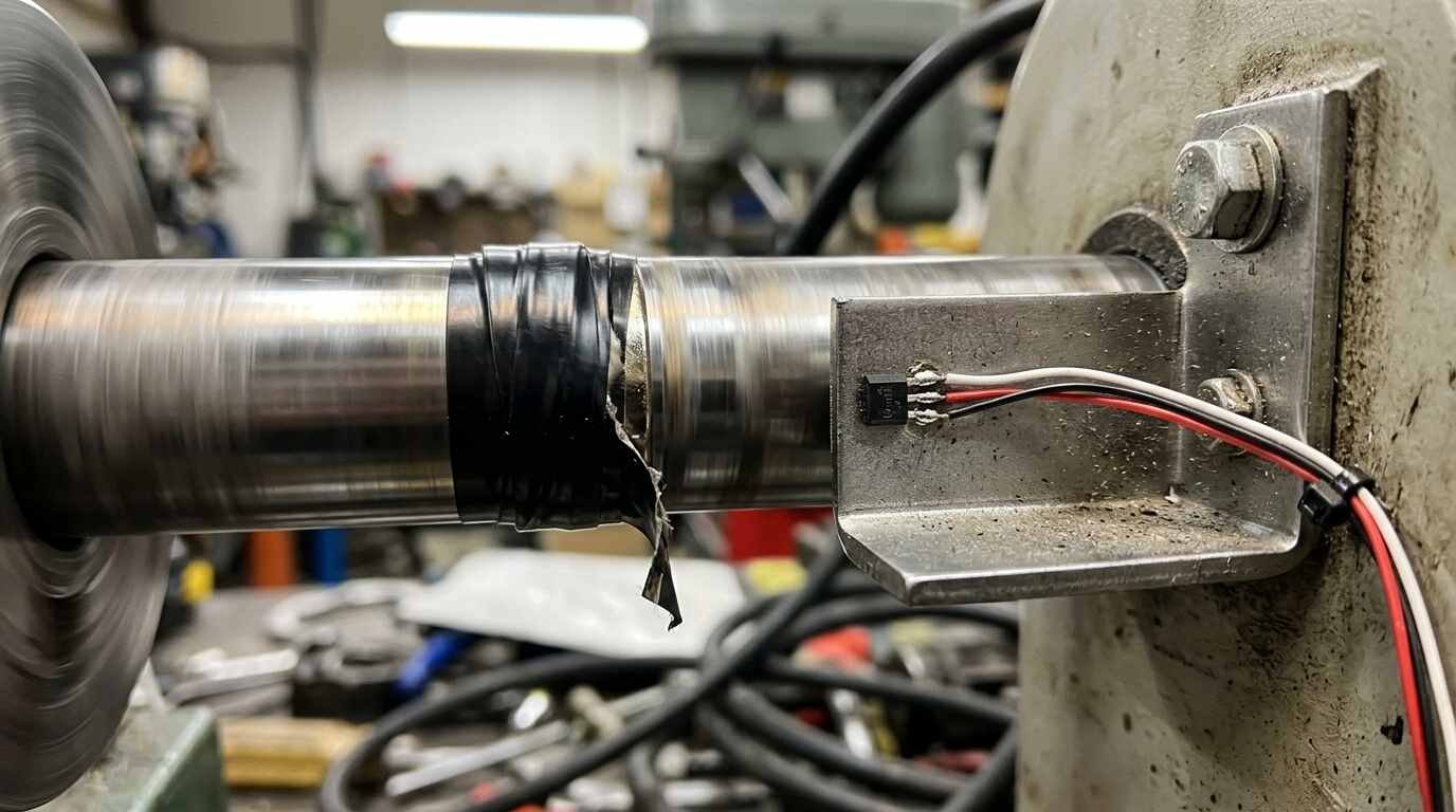
- A small permanent magnet, glued or taped to the rotating part. The datasheet describes the family as activated by small commercially available permanent magnets.
- An Arduino Uno or another board with interrupt-capable pins. On the Uno Rev3 those are pins 2 and 3.
- Jumper wires. No specific retail listing is linked, because none could be verified on the retailer’s own page.
Wire the sensor’s supply pin to 5 V, ground to ground, and the output to pin 2. Because the output is open collector, it can only pull the line low; something must pull it high otherwise. The datasheet says a suitable pull-up lets it drive bipolar or CMOS logic. The Arduino reference notes the ATmega has internal pull-up resistors that you enable by passing INPUT_PULLUP to pinMode(), which avoids an external part. Our Elegoo UNO R3 starter kit review describes a kit with a UNO R3-compatible board, a breadboard and jumper wires, which covers the board and wiring side of this circuit. Check any kit’s parts list for a Hall switch before assuming one is inside.
Interrupts, volatile and micros
Polling a pin in loop() misses pulses whenever the loop is busy. An interrupt does not. The Arduino reference recommends attachInterrupt(digitalPinToInterrupt(pin), ISR, mode), with modes LOW, CHANGE, RISING and FALLING. Because the Hall output drops when the magnet arrives, FALLING marks the start of each pulse.
The routine that runs on each interrupt, the ISR, lives under rules. Inside it, delay() will not work and millis() will not increment. micros() works initially but behaves erratically after 1 to 2 milliseconds, so the ISR must be brief: read the clock, do a subtraction, store, leave.
Variables shared between the ISR and loop() need the volatile qualifier. For anything larger than a byte there is a second hazard on an 8-bit chip: loop() may read half the bytes before the interrupt rewrites the rest. The Arduino reference’s remedy is to disable interrupts during the read, either with noInterrupts() or the ATOMIC_BLOCK macro from util/atomic.h.
As for the clock, micros() returns an unsigned long, has a resolution of four microseconds on 16 MHz boards, and overflows after approximately 70 minutes. Unsigned subtraction handles that wraparound correctly as long as the interval itself is short.
#include <util/atomic.h>

const byte SENSOR_PIN = 2;                   // interrupt pin on Uno Rev3
const byte MAGNETS = 1;                      // magnets per revolution
const unsigned long MIN_PERIOD_US = 2500;    // ignore pulses closer than this
const unsigned long TIMEOUT_US = 1000000UL;  // no pulse for 1 s -> RPM = 0

volatile unsigned long lastPulseUs = 0;
volatile unsigned long periodUs = 0;

void onPulse() {
  unsigned long now = micros();
  unsigned long dt = now - lastPulseUs;
  if (dt < MIN_PERIOD_US) return;            // glitch guard
  if (lastPulseUs != 0) periodUs = dt;
  lastPulseUs = now;
}

void setup() {
  Serial.begin(115200);
  pinMode(SENSOR_PIN, INPUT_PULLUP);
  attachInterrupt(digitalPinToInterrupt(SENSOR_PIN), onPulse, FALLING);
}

void loop() {
  unsigned long p, last, now;
  ATOMIC_BLOCK(ATOMIC_RESTORESTATE) {
    p = periodUs;
    last = lastPulseUs;
    now = micros();
  }
  float rpm = 0.0;
  if (p > 0 && (now - last) < TIMEOUT_US) {
    rpm = 60000000.0 / p / MAGNETS;
  }
  Serial.println(rpm, 1);
  delay(200);
}
The arithmetic, worked
One minute holds 60,000,000 microseconds. If the pulses are P microseconds apart and the shaft carries N magnets, the shaft makes one revolution every N × P microseconds, so RPM = 60,000,000 / (N × P).
- P = 37,500 µs, one magnet: 60,000,000 / 37,500 = 1,600 RPM.
- P = 37,500 µs, two magnets: 60,000,000 / 75,000 = 800 RPM.
- P = 3,000 µs, one magnet: 60,000,000 / 3,000 = 20,000 RPM.
The 4 µs clock step puts a floor under the precision. At 37,500 µs a one-step error is about 0.011 percent. At 3,000 µs it grows to about 0.13 percent. Measuring the period of a single revolution, in other words, gets less exact as the shaft speeds up, which is the reverse of the counting method that tallies pulses in a fixed window. A one-second window with one magnet resolves to 60 RPM, since one extra pulse in that second equals 60 revolutions per minute.
The two methods suit different jobs. Period timing responds within one revolution and handles slow shafts well. Gate counting averages across many pulses and handles fast ones. The tunnel detector in our piece on cosmic-ray muons and ocean tides is the same idea at another scale: counted events, compared hour by hour, become a physical measurement.
Noise and false triggers
A Hall switch has no contacts, so classic switch bounce does not occur, and the built-in hysteresis rejects small wiggles in the field. What remains is electrical pickup on long wires and a magnet that wobbles near the threshold. Two software guards in the sketch address this. MIN_PERIOD_US discards any pulse closer than the fastest plausible spacing; for a one-magnet shaft limited to 12,000 RPM, the minimum period is 60,000,000 / 12,000 = 5,000 µs, so the 2,500 µs guard leaves a margin of two. The timeout reports zero when no pulse arrives for a second, so a stopped shaft does not display its last speed forever.
Choose the guard from your own maximum speed; the numbers here are placeholders for that calculation, not recommendations for any real machine. Keep the sensor wires short, since long runs pick up electrical interference more easily, and mount the magnet so that it passes the sensor face at a fixed small distance each turn, because a magnet that arrives weaker on some revolutions will cross the operate point late or not at all.
Sources