





How the green PS_ON wire starts an ATX supply, which wires carry 3.3, 5 and 12 V, why a minimum load matters, and the mains and stored-energy limits that mean you should never open the case.
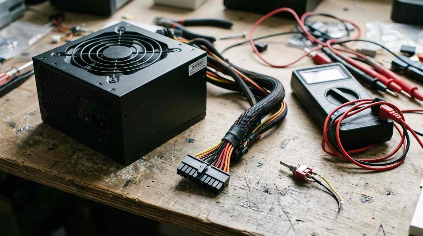
Three fixed DC voltages, a pile of connectors and a fan: that is what a retired desktop power supply still offers. Wikipedia’s ATX entry says the specification requires the supply to produce three main outputs, +3.3 V, +5 V and +12 V, plus a standby rail, and the same wires that powered a motherboard can run LEDs, small motors or a breadboard.
The conversion needs one wire jumpered and one load attached. It also carries real hazards, because the box contains mains-voltage circuitry that never stops being dangerous just because the cover is on. This guide leads with those limits, then covers the pinout, the control signal, the load requirement and a build order.
Safety limits come first
Do not open the supply. The switched-mode power supply article says the main filter capacitor “will often store up to 325 volts long after the input power has been disconnected,” that not all supplies contain a bleeder resistor to discharge it, and that contact can result in a severe electrical shock. It adds that in both linear and switch-mode supplies, “mains, and possibly the output voltages, are hazardous.”
Isolation is not a guarantee either. The same article notes that supplies with transformers can still be dangerous if the insulation between primary and secondary breaks down. Nothing in the build below requires removing the cover, so do not.
Unplugging matters. According to the computer PSU article, the front-panel switch only sends a control signal and does not switch mains voltage, and a supply connected to mains always provides 5 V standby even when the computer is nominally off. Treat a plugged-in supply as live, whether or not the fan is turning.
Output wiring has its own risk. The same article warns that short circuits can cause serious damage, melt wire insulation or start a fire. Intel design guidance sets a ceiling: ATX12V Power Supply Design Guide 2.2 says no output shall continuously provide more than 240 VA under any load condition, including a short circuit. That is a limit on energy, not a promise that nothing will overheat at 240 VA.
What each wire gives you
Wire colors on the 24-pin connector, as listed in the computer PSU article, follow a pattern worth memorizing before touching anything.
| Color | Function |
|---|---|
| Orange | +3.3 V (brown is the 3.3 V sense line) |
| Red | +5 V |
| Yellow | +12 V |
| Blue | -12 V (legacy) |
| Purple | +5 V standby |
| Grey | Power good (PWR_OK) |
| Green | Power on (PS_ON), pin 16 |
| Black | Ground |
The ATX article adds that the 24-pin ATX12V 2.x connector has four extra pins over the older layout, giving one additional 3.3 V, 5 V and 12 V circuit. That is why several wires of each color appear on the connector.
The article also cautions that modular PSU cables must only be used with the model they came with, because mismatched pin assignments can put 12 V on a 5 V or 3.3 V pin. It singles out another trap: the 8-pin PCIe connector and the 8-pin EPS12V connector look alike but swap 12 V and ground positions, so a mix-up can short the supply.
The green-wire trick, explained
Inside the supply, the PS_ON line is held up to +5 V. Grounding it tells the supply to start. The ATX article describes PS_ON# as an active-low signal from the motherboard that is pulled up internally, and Intel-derived guidance says that while it is high the DC output rails must not deliver current and must be held at zero potential. The standby rail stays on regardless, as long as AC is present.
So the “trick” is not a trick at all; it is the motherboard’s job, done by hand. Connect the green wire to a black wire, either permanently or through a switch, and the supply behaves as if a motherboard asked for power. The ATX12V 2.2 guide gives the input-low limit as 0.8 V maximum, so a direct wire-to-ground connection sits comfortably inside it.
After PS_ON# goes low, the grey PWR_OK wire stays low briefly. The ATX article gives 100 to 500 ms for the delay, and the Intel 2.1a guide lists the same required window. A short gap before PWR_OK rises is expected, not a fault.
Why the supply wants a load
A supply with nothing attached may behave oddly, and the standards say why. ATX states that “a minimum load on one or more voltages may be required (varies by model and vendor).” The ATX12V 2.2 guide says no damage or hazardous condition should occur with all DC connectors disconnected from the load, yet the power supply “may latch into the shutdown state.”
The sources give no universal minimum, so the supply’s own label and manual are the authority. Power arithmetic still helps size a dummy load. A 5 V rail across a 10 ohm resistor carries 0.5 A and dissipates 2.5 W, which means a resistor rated well above 2.5 W.
Reading the control signals
Two signals tell you what the supply is thinking. PS_ON# is the input you control. PWR_OK is the output that reports status. Intel’s 2.1a guide specifies the PWR_OK logic levels: low is below 0.4 V while sinking 4 mA, and high lies between 2.4 V and 5 V while sourcing 200 microamps. If a meter on the grey wire reads in that high band a moment after the switch closes, the supply considers its outputs stable.
The standby rail deserves its own mention. Because +5VSB is always enabled whenever AC power is present, per the Intel guide, the purple wire reads about 5 V with the switch open. That is normal, and it is one more reminder that “off” at the switch is not “off” at the wall.
If it does not start
| Symptom | Candidate cause | Source basis |
|---|---|---|
| Fan never spins | Green wire not actually connected to ground, or no AC | PS_ON# must be driven low to start |
| Starts, then shuts down | No load on the outputs | ATX12V 2.2 says the supply may latch into shutdown |
| Starts only with a load | Minimum load required | ATX: minimum load on one or more voltages may be required |
| Purple wire live with switch open | Normal standby behavior | +5VSB is always on with AC present |
One more figure from the Intel 2.1a guide explains why large supplies carry several 12 V rails: current levels on the 12 V rail above 18 amps must be divided into multiple rails, tied to the 240 VA energy-hazard requirement. If a label shows a rated 12 V total, check whether it is split before assuming a single rail can deliver it.
Build order
- Unplug the supply and leave the cover on.
- Identify the 24-pin connector and confirm the green wire against the pin 16 position and the color table.
- Join the green wire to an adjacent black wire through a switch, or a deliberate jumper, so power can be removed without unplugging.
- Attach a load to the rail you plan to use, with a rating that suits the voltage and current.
- Plug in, close the switch, and read the rails at the connector with a meter. The orange, red and yellow wires should read near 3.3, 5 and 12 V.
- Open the switch, then unplug the supply before changing any wiring.
Readers weighing portable alternatives can compare the Anker 737 power bank or the cells inside the Kobalt TXP battery.
What the converted supply cannot do
Rails are fixed: this is a source of 3.3, 5 and 12 V, not an adjustable bench supply. The sources reviewed give no ripple or accuracy figures for the converted use, so they are left out here. The 240 VA limit per output, and the minimum-load requirement, set the practical ceiling.
Sources